
A little more than a year ago, we started developing our professional slide-scanning microscope, internally called FRAME (fast widget augmented microscope engine). From day one, it was obvious that the real challenges were not only in optics and mechanics, but equally in electronics and the underlying software architecture.
More information about this in our preprint: https://arxiv.org/pdf/2510.22552
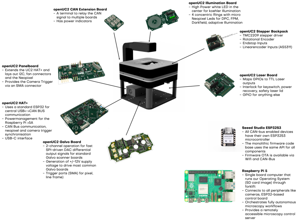
Christian, our electronics developer who has been with us since day one, pushed early for using the ESP32 as the core microcontroller and made it the heart of our electronics box . Together with our open-source community developer Ingo, we initially built a monolithic firmware: a single codebase capable of driving many different hardware configurations, all tightly coupled to a specific firmware version. It’S open-source and can be accessed here: https://github.com/youseetoo/uc2-esp32
This worked surprisingly well, until we hit a very practical limit. The electronics box can host at most four stepper motor drivers. As soon as we moved toward more complex setups, multiple axes, lasers, LED matrices, galvos, and human-interface devices, this approach no longer scaled.
Thinking Modular Beyond Optics
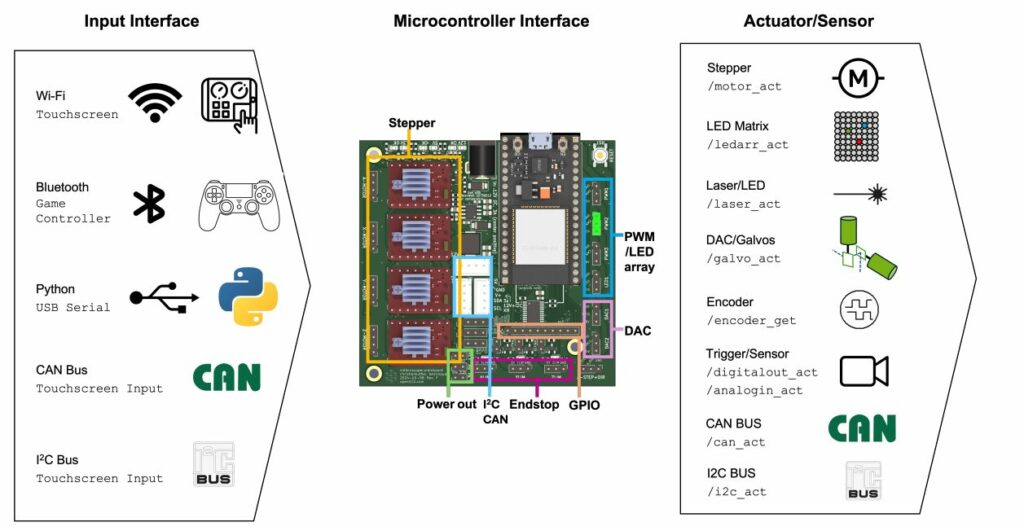
Our entire platform is built around modular optics, so it was only logical to apply the same philosophy to electronics. The goal became a distributed system where every motor, laser, or interface node has its own microcontroller and can run local control loops continuously, for example encoder-based motion control, without pushing a single central CPU to its limits.
An early attempt using I2C failed quickly. It is not particularly robust, not very friendly in 12-volt environments, and does not scale well with cable length or node count.
Looking at industrial systems made the solution obvious: CAN bus, the same technology used for communication inside cars and industrial machines.
The CAN Bus Architecture
After more than a year of iterations and many internal discussions about how far modularity should go, we now have a robust system based on CAN bus. Every participant on the bus has its own CAN ID and is individually addressable.
In practice, this means the system can be extended almost arbitrarily:
multiple motors, multiple lasers, LED matrices, galvos, joysticks, M5Stack-style interfaces, all on the same bus. A simplified view of the bus looks like this:
The ecosystem of different Seeed Studio Xiao ESP32S3 boards that are communicating through the “Master” using the TWAI/CAN-Bus.
Host / Master (ESP32, USB or WiFi)
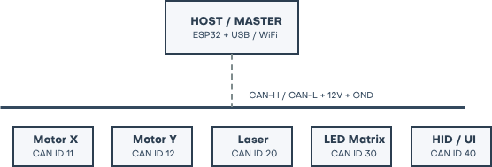
Each node is autonomous, knows its role, and communicates through clearly defined messages.
One API, Two Transports
A key design decision was to avoid duplicating complexity. The logical API used over CAN is the same one we use on the serial interface.
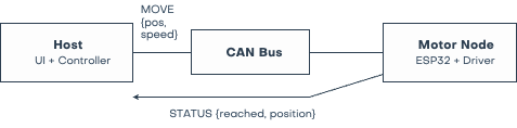
Only the transport layer changes.
On the host side, parameters are packed into structured messages and sent to a specific CAN ID. On the client side, these structures are parsed and forwarded to the internal driver logic. This allows us to either send full configurations or update individual parameters, fast and with minimal bandwidth.
The user interface is informed via events, without polling and without fragile timing assumptions.
OTA Firmware Updates via CAN
A distributed system is only usable if every node can be kept up to date. APIs evolve, bugs are fixed, features are added. Manually flashing each node via USB is not an option. Our solution combines CAN and WiFi.
CAN is used to trigger the update process reliably. The actual firmware transfer then happens over WiFi, which is much faster than streaming megabytes of data over CAN alone.
The OTA process works conceptually like this:
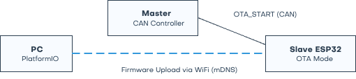
Why not WiFi only? Because WiFi is not always available or stable. Some devices were initially shipped without antennas. CAN, on the other hand, is deterministic and robust. It always works.
Once in OTA mode, a device announces itself via mDNS, for example as UC2-CAN-B.local, and can be flashed directly using PlatformIO, the Arduino IDE, or espota.py.
Hybrid Boards and Flexible Deployment
Some of our boards are hybrid by design. They can run as standalone controllers via USB or serial, or act as full CAN nodes.
Depending on the CAN ID and address range, a motor can be controlled locally or remotely over the bus. The same firmware supports both modes. This lets us start simple and scale later without changing the underlying architecture.
More inforamtion available here: https://docs.openuc2.com/dev/hw/electronics/uc2-standalone-board/schematics-v4
A Foundation for the Entire Platform
The CAN bus system is not specific to FRAME. It is the foundation for our entire optics and electronics ecosystem.
Motors, lasers, illumination, and interfaces all run as modular, distributed nodes. The host always has a coherent view of the system state, while each node remains responsible for its real-time tasks.
The full codebase is open source as part of openUC2. We are actively building on this architecture and welcome feedback, contributions, and new ideas. If you are curious or want to get involved, feel free to reach out.
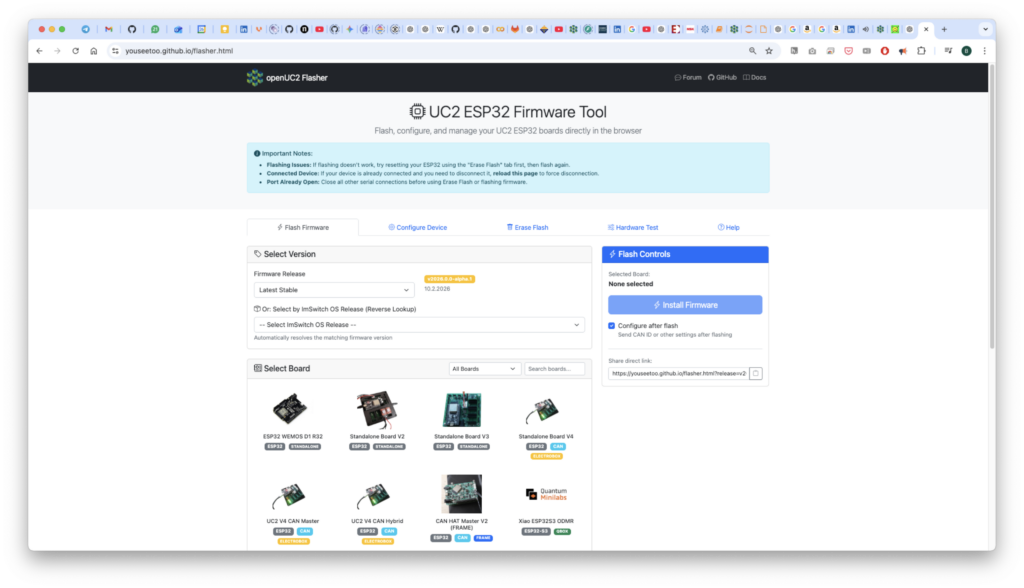
The firmware is open-source and can be flashed/operated in the browser here https://youseetoo.github.io/flasher.html: